BlockSim Analytical Examples: Difference between revisions
Lisa Hacker (talk | contribs) |
Lisa Hacker (talk | contribs) |
||
| Line 1: | Line 1: | ||
=Example 15= | =Example 15= | ||
Revision as of 02:39, 16 August 2012
Example 15
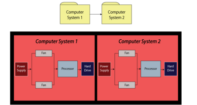
For this example, obtain the reliability equation of the system shown in Figure fig29.
Solution to Example 15
The system reliability equation is:
- [math]\displaystyle{ {{R}_{System}}={{R}_{Computer1}}\cdot {{R}_{Computer2}} }[/math]
- Now:
- [math]\displaystyle{ \begin{align} {{R}_{Computer1}}= & ({{R}_{Power\,Supply}}\cdot {{R}_{Processor}}\cdot {{R}_{HardDrive}} \\ &\cdot(-{{R}_{Fan}}\cdot {{R}_{Fan}}+{{R}_{Fan}}+{{R}_{Fan}})) \end{align} }[/math]
Since the structures of the computer systems are the same, [math]\displaystyle{ {{R}_{Computer1}}={{R}_{Computer2}} }[/math] , then substituting Eqn. (excomp2a) into Eqn. (excomp) yields:
- [math]\displaystyle{ \begin{align} {{R}_{System}}= & ({{R}_{Power\,Supply}}\cdot {{R}_{Processor}}) \\ & \cdot {{R}_{HardDrive}}(-R_{Fan}^{2}+2{{R}_{Fan}}){{)}^{2}} \end{align} }[/math]
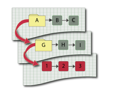
When using BlockSim to compute the equation, the software will return Eqn. (excomp) for the system and Eqn. (excomp2a) for the subdiagram. Even though BlockSim will make these substitutions internally when performing calculations, it does show them in the System Reliability Equation window.
Example 16
In the diagram shown in Figure Fig32, electricity can flow in both directions. Successful system operation requires at least one output (O1, O2 or O3) to be working.
Create a block diagram for this system.
Solution to Example 16
The bidirectionality of this system can be modeled using mirrored blocks. The diagram is shown in Figure fig33a.
Blocks 5A, 7A and 1A are duplicates (or mirrored blocks) of 5, 7 and 1 respectively.
Example 18
Assume that a system has six failure modes: A, B, C, D, E and F. Furthermore, assume that failure of the entire system will occur if:
- • Mode B, C or F occurs.
- • Modes A and E, A and D or E and D occur.
Draw the block diagram and obtain the reliability equation.
Solution to Example 18
The diagram is shown in Figure fig35
The reliability equation, as obtained from BlockSim is:
- [math]\displaystyle{ \begin{align} {{R}_{System}}= & (-2{{R}_{A}}\cdot {{R}_{B}}\cdot {{R}_{C}}\cdot {{R}_{D}}\cdot {{R}_{2/3}}\cdot {{R}_{E}}\cdot {{R}_{F}} \\ & +{{R}_{A}}\cdot {{R}_{B}}\cdot {{R}_{C}}\cdot {{R}_{D}}\cdot {{R}_{2/3}}\cdot {{R}_{F}} \\ & +{{R}_{A}}\cdot {{R}_{B}}\cdot {{R}_{C}}\cdot {{R}_{2/3}}\cdot {{R}_{E}}\cdot {{R}_{F}} \\ & +{{R}_{B}}\cdot {{R}_{C}}\cdot {{R}_{D}}\cdot {{R}_{2/3}}\cdot {{R}_{E}}\cdot {{R}_{F}}) \end{align} }[/math]
The BlockSim equation includes the node reliability term [math]\displaystyle{ {{R}_{2/3}}, }[/math] which cannot fail, or [math]\displaystyle{ {{R}_{2/3}}=1 }[/math] . This can be removed, yielding:
- [math]\displaystyle{ \begin{align} {{R}_{System}}= & (-2{{R}_{A}}\cdot {{R}_{B}}\cdot {{R}_{C}}\cdot {{R}_{D}}\cdot {{R}_{E}}\cdot {{R}_{F}} \\ & +{{R}_{A}}\cdot {{R}_{B}}\cdot {{R}_{C}}\cdot {{R}_{D}}\cdot {{R}_{F}} \\ & +{{R}_{A}}\cdot {{R}_{B}}\cdot {{R}_{C}}\cdot {{R}_{E}}\cdot {{R}_{F}} \\ & +{{R}_{B}}\cdot {{R}_{C}}\cdot {{R}_{D}}\cdot {{R}_{E}}\cdot {{R}_{F}}) \end{align} }[/math]

