State Change Triggers: Difference between revisions
Lisa Hacker (talk | contribs) No edit summary |
Lisa Hacker (talk | contribs) No edit summary |
||
| (40 intermediate revisions by 4 users not shown) | |||
| Line 1: | Line 1: | ||
<noinclude>{{Banner BlockSim Articles}}{{Navigation box}} | <noinclude>{{Banner BlockSim Articles}}{{Navigation box}} | ||
''This article | ''This article also appears in the [https://help.reliasoft.com/reference/system_analysis System analysis reference].'' | ||
</noinclude> | </noinclude> | ||
Consider a case where you have two generators, and one (A) is primary while the other (B) is standby. If A fails, you will turn B on. When A is repaired, it then becomes the standby. State change triggers (SCT) allow you to simulate this case. You can specify events that will activate and/or deactivate the block during simulation. The figure below shows the options for state change triggers in the Block Properties window. | Consider a case where you have two generators, and one (A) is primary while the other (B) is standby. If A fails, you will turn B on. When A is repaired, it then becomes the standby. State change triggers (SCT) allow you to simulate this case. You can specify events that will activate and/or deactivate the block during simulation. The figure below shows the options for state change triggers in the Block Properties window. | ||
[[Image:State Change Trigger Options.png|center| | [[Image:State Change Trigger Options.png|center|600px|link=]] | ||
Once you have enabled state change triggers for a block, there are several options. | Once you have enabled state change triggers for a block, there are several options. | ||
| Line 15: | Line 15: | ||
The State Change Trigger window is shown in the figure below: | The State Change Trigger window is shown in the figure below: | ||
[[Image:State_change_trigger_window.png|center|500px]] | [[Image:State_change_trigger_window.png|center|500px|link=]] | ||
== Assumptions == | == Assumptions == | ||
| Line 26: | Line 26: | ||
**Default off unless SCT overridden: Upon restoration, the block will be off unless a request is made to turn this block on while the block is down and the request is still applicable at the time of restoration | **Default off unless SCT overridden: Upon restoration, the block will be off unless a request is made to turn this block on while the block is down and the request is still applicable at the time of restoration | ||
*Maintenance while block is off: Maintenance tasks will be performed. At the end of the maintenance, "upon restoration" rules will be checked to determine the state of the block. | *Maintenance while block is off: Maintenance tasks will be performed. At the end of the maintenance, "upon restoration" rules will be checked to determine the state of the block. | ||
*Assumptions for phases: | *Assumptions for phases: In Versions 10 and earlier, the state of a block (on/off) was determined at the beginning of each phase based on the "Initial state" setting of the block for that phase. Starting in Version 11, the state of the block transfers across phases instead of resetting based on initial settings. | ||
*If there are multiple triggering requests put on a block when it is down, only the latest one is considered. The latest request will cancel all requests before it. For example, Block A fails at 20 and is down until 70. Block B fails at 30 and Block C fails at 40. Block A has state change triggers enabled such that it will be activated when Block B fails and it will be deactivated when Block C fails. Thus from 20 to 70, at 30, Block B will put a request on Block A to turn it ON and at 40, Block C will put another request to turn it OFF. In this case, according to our assumption, the request from Block C at 40 will cancel the request from Block B at 30. In the end, only the request from Block C will be considered. Thus, Block A will be turned OFF at 70 when it is done with repair. | *If there are multiple triggering requests put on a block when it is down, only the latest one is considered. The latest request will cancel all requests before it. For example, Block A fails at 20 and is down until 70. Block B fails at 30 and Block C fails at 40. Block A has state change triggers enabled such that it will be activated when Block B fails and it will be deactivated when Block C fails. Thus from 20 to 70, at 30, Block B will put a request on Block A to turn it ON and at 40, Block C will put another request to turn it OFF. In this case, according to our assumption, the request from Block C at 40 will cancel the request from Block B at 30. In the end, only the request from Block C will be considered. Thus, Block A will be turned OFF at 70 when it is done with repair. | ||
==Example: | ==Example: Using SCT for Standby Rotation== | ||
{{:Example_Using_SCT_for_Standby_Rotation}} | |||
<div class="noprint"> | |||
{{Examples Box|BlockSim Examples|<p>More examples are available for using State Change Triggers (SCTs) in simulation diagrams. See also:</p>{{Examples Link|Example_Using_SCT_to_Analyze_Tire_Maintenance|Using SCT to Analyze Tire Maintenance}}{{Examples Link|Example_Using_SCT_to_Analyze_Standby_with_Delay|Using SCT to Analyze Standby with Delay}}{{Examples Link|Example_Using_SCT_to_Model_Two_Standby_Blocks|Using SCT to Model Two Standby Blocks}}{{Examples Link|Example_Demonstrating_the_State_Upon_Repair_Option_for_SCT|SCT: The State Upon Repair Option}}{{Examples Link|BlockSim_Example:_Default_OFF_unless_SCT_Overridden|Default OFF Unless SCT Overridden}}{{Examples Link|BlockSim_Example:_Default_OFF_unless_SCT_Overridden|Default OFF Unless SCT Overridden}}}} | |||
</div> | |||
= | |||
Latest revision as of 21:33, 18 September 2023
 |
This article also appears in the System analysis reference.
Consider a case where you have two generators, and one (A) is primary while the other (B) is standby. If A fails, you will turn B on. When A is repaired, it then becomes the standby. State change triggers (SCT) allow you to simulate this case. You can specify events that will activate and/or deactivate the block during simulation. The figure below shows the options for state change triggers in the Block Properties window.
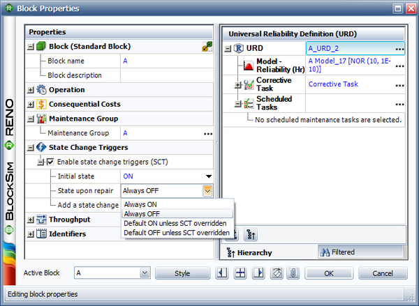
Once you have enabled state change triggers for a block, there are several options.
- Initial state allows you to specify the initial state for the block, either ON or OFF.
- State upon repair allows you to specify the state of the block after its repair. There are four choices: Always ON, Always OFF, Default ON unless SCT Overridden and Default OFF unless SCT Overridden. In the Assumptions sections, we will explain what these choices mean and illustrate them using an example.
- Add a state change trigger allows you to add a state change trigger to the block.
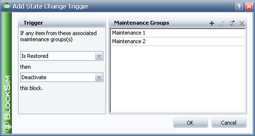
The state change trigger can either activate or deactivate the block when items in specified maintenance groups go down or are restored. To define the state change trigger, specify the triggering event (i.e., an item goes down or an item is restored), the state change (i.e., the block is activated or deactivated) and the maintenance group(s) in which the triggering event must happen in order to trigger the state change. Note that the current block does not need to be part of the specified maintenance group(s) to use this functionality.
The State Change Trigger window is shown in the figure below:
Assumptions
- A block cannot trigger events on itself. For example, if Block 1 is the only block that belongs to MG 1 and Block 1 is set to be turned ON or OFF based on MG 1, this trigger is ignored.
- OFF events cannot trigger other events. This means that things cannot be turned OFF in cascade. For example, if Block 1 going down turns OFF Block 2 and Block 2 going down turns OFF Block 3, a failure by Block 1 will not turn OFF Block 3. Block 3 would have to be directly associated with downing events of Block 1 for this to happen. The reason for this restriction is that allowing OFF events to trigger other events can cause circular reference problems. For example, four blocks A, B, C and D are in parallel. Block A belongs to MG A and initially it is ON. Block B belongs to MG B and its initial status is also ON. Block C belongs to MG C and its initial status is OFF. Block D belongs to MG D and its initial status is ON. A failure of Block A will turn OFF Block B. Then Block B will turn Block C ON and finally C will turn OFF Block D. However, if an OFF event for Block D will turn Block B ON, and an ON event for Block B will turn Block C OFF, and an OFF event for Block C will turn Block D ON, then there is a circular reference problem.
- Upon restoration states:
- Always ON: Upon restoration, the block will always be on.
- Always OFF: Upon restoration, the block will always be off.
- Default ON unless SCT overridden: Upon restoration, the block will be on unless a request is made to turn this block off while the block is down and the request is still applicable at the time of restoration. For example, assume Block A's state upon repair is ON unless SCT overridden. If a failure of Block B triggers a request to turn Block A off but Block A is down, when the maintenance for Block A is completed, Block A will be turned off if Block B is still down.
- Default off unless SCT overridden: Upon restoration, the block will be off unless a request is made to turn this block on while the block is down and the request is still applicable at the time of restoration
- Maintenance while block is off: Maintenance tasks will be performed. At the end of the maintenance, "upon restoration" rules will be checked to determine the state of the block.
- Assumptions for phases: In Versions 10 and earlier, the state of a block (on/off) was determined at the beginning of each phase based on the "Initial state" setting of the block for that phase. Starting in Version 11, the state of the block transfers across phases instead of resetting based on initial settings.
- If there are multiple triggering requests put on a block when it is down, only the latest one is considered. The latest request will cancel all requests before it. For example, Block A fails at 20 and is down until 70. Block B fails at 30 and Block C fails at 40. Block A has state change triggers enabled such that it will be activated when Block B fails and it will be deactivated when Block C fails. Thus from 20 to 70, at 30, Block B will put a request on Block A to turn it ON and at 40, Block C will put another request to turn it OFF. In this case, according to our assumption, the request from Block C at 40 will cancel the request from Block B at 30. In the end, only the request from Block C will be considered. Thus, Block A will be turned OFF at 70 when it is done with repair.
Example: Using SCT for Standby Rotation
This example illustrates the use of state change triggers in BlockSim (Version 8 and above) by using a simple standby configuration. Note that this example could also be done using the standby container functionality in BlockSim.
More specifically, the following settings are illustrated:
- State Upon Repair: Default OFF unless SCT overridden
- Activate a block if any item from these associated maintenance group(s) goes down
Problem Statement
Assume three devices A, B and C in a standby redundancy (or only one unit is needed for system operation). The system begins with device A working. When device A fails, B is turned on and repair actions are initiated on A. When B fails, C is turned on and so forth.
BlockSim Solution
The BlockSim model of this system is shown in the figure below.
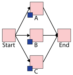
- The failure distributions of all three blocks follow a Weibull distribution with Beta = 1.5 and Eta = 1,000 hours.
- The repair distributions of the three blocks follow a Weibull distribution with Beta = 1.5 and Eta = 100 hours.
- After repair, the blocks are "as good as new."
There are three maintenance groups, 2_A, 2_B and 2_C, set as follows:
- Block A belongs to maintenance group 2_A.
- It has a state change trigger.
- The initial state is ON and the state upon repair is "Default OFF unless SCT overridden."
- If any item from maintenance group 2_C goes down, then activate this block.
- It has a state change trigger.
- Block B belongs to maintenance group 2_B.
- It has a state change trigger.
- The initial state is OFF and the state upon repair is "Default OFF unless SCT overridden."
- If any item from maintenance group 2_A goes down, then activate this block.
- It has a state change trigger.
- Block C belongs to maintenance group 2_C.
- It has a state change trigger.
- The initial state is OFF and the state upon repair is "Default OFF unless SCT overridden."
- If any item from maintenance group 2_B goes down, then activate this block.
- It has a state change trigger.
- All blocks A, B and C are as good as new after repair.
System Events
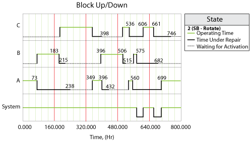
The system event log for a single run through the simulation algorithm is shown in the Block Up/Down plot below, and is as follows:
- At 73 hours, Block A fails and activates Block B.
- At 183 hours, Block B fails and activates Block C.
- At 215 hours, Block B is done with repair. At this time, Block C is operating, so according to the settings, Block B is standby.
- At 238 hours, Block A is done with repair. At this time, Block C is operating. Thus Block A is standby.
- At 349 hours, Block C fails and activates Block A.
- At 396 hours, Block A fails and activates Block B.
- At 398 hours, Block C is done with repair. At this time, Block B is operating. Thus Block C is standby.
- At 432 hours, Block A is done with repair. At this time, Block B is operating. Thus Block A is standby.
- At 506 hours, Block B fails and activates Block C.
- At 515 hours, Block B is done with repair and stays standby because Block C is operating.
- At 536 hours, Block C fails and activates Block A.
- At 560 hours, Block A fails and activates Block B.
- At 575 hours, Block B fails and makes a request to activate Block C. However, Block C is under repair at the time. Thus when Block C is done with repair at 606 hours, the OFF setting is overridden and it is operating immediately.
- At 661 hours, Block C fails and makes a request to activate Block A. However, Block A is under repair at the time. Thus when Block A is done with repair at 699 hours, the OFF setting is overridden and it is operating immediately.
- Block B and Block C are done with repair at 682 hours and at 746 hours respectively. However, at these two time points, Block A is operating. Thus they are both standby upon repair according to the settings.