Template:Rotation
Standby Rotation Example
Purpose
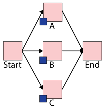
This example illustrates the use of state change triggers SCT in BlockSim Version 8 by using a simple standby configuration. Note that this example could also be done using the standby container functionality in BlockSim.
More specifically the following settings are illustrated:
- State Upon Repair: Default OFF unless SCT overridden
- Activate a block if any item from these associated maintenance group(s) goes down
Statement
Assume three devices A, B and C in a standby redundancy (or only one unit is needed for system operation). The system begins with device A working. When device A fails B is turned on and repair actions initiated on A. When B fails C is turned on and so forth.
BlockSim Solution
The BlockSim model of this system is shown in the Figure below.
- The failure distributions of all three blocks follow Weibull distribution with Beta = 1.5 and Eta = 1,000.
- The repair distribution of three blocks also follows Weibull distribution with Beta = 1.5 and Eta = 100.
- After repair, they are "as good as new".
There are three maintenance groups, 2_A, 2_B and 2_C set as follows:
- Block A belongs to maintenance group 2_A.
- It has state change trigger.
- The initial state is ON and the state upon repair is "Default Off Unless overridden".
- If any item from maintenance group 2_C goes down, then activate this block.
- It has state change trigger.
- Block B belongs to maintenance group 2_B.
- It has state change trigger.
- The initial state is OFF and the state upon repair is "Default Off Unless overridden".
- If any item from maintenance group 2_A goes down, then activate this block.
- It has state change trigger.
- Block C belongs to maintenance group 2_C.
- It has state change trigger.
- The initial state is OFF and the state upon repair is "Default Off Unless overridden".
- If any item from maintenance group 2_B goes down, then activate this block.
- It has state change trigger.
- All blocks A, B and C are as good as new after repair.
System Events
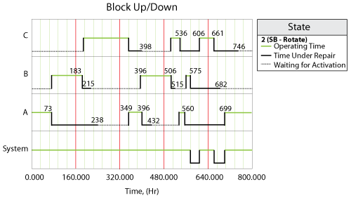
The system event log is shown Block Up/Down plot below, for a single run through the simulation algorithm and is as follows:
- At 73, Block A fails and activates Block B.
- At 183, Block B fails and activates Block C.
- At 215, Block B is done with repair. At this time, Block C is operating, according to setting, Block B is standby.
- At 238, Block A is done with repair. At this time, Block C is operating. Thus Block A is standby.
- At 349, Block C fails and activates Block A.
- At 396, Block A fails and activates Block B.
- At 398, Block C is done with repair. At this time, Block B is operating. Thus Block C is standby.
- At 432, Block A is done with repair. At this time, Block B is operating. Thus Block A is standby.
- At 506, Block B fails and activates Block C.
- At 515, Block B is done with repair and keep standby because Block C is operating.
- At 536, Block C fails and active Block A.
- At 560, Block A fails and active Block B.
- At 575, Block B fails and put a request to active Block C. However, Block C is under repair at the time. Thus when Block C is done with repair at 606, the OFF setting is overwritten and it is operating immediately.
- At 661, Block C fails and put a request to active Block A. However, Block A is under repair at the time. Thus when Block A is done with repair at 699, the OFF setting is overwritten and it is operating immediately.
- Block B and Block C are done with repair at 682 and at 746 respectively. However, at these two time point, Block A is operating. Thus they are both standby upon repair according to settings.

